- 您现在的位置:买卖IC网 > Sheet目录2008 > MAX1361MEUB+T (Maxim Integrated Products)IC SYSTEM MON 10BIT 4CH 10-UMAX
MAX1361/MAX1362
Reading a Conversion (Read Cycle)
Initiate a read cycle to start a conversion sequence and
to obtain conversion results. See the
Scan Modes
section for details on the channel-scan sequence. Read
cycles begin with the bus master issuing a START
condition followed by 7 address bits and a read bit
(R/W = 1). After successfully receiving the address byte,
the MAX1361/MAX1362 (slave) issue an ACK. The master
then reads from the slave. (See Figures 10–13.)
The result is transmitted in 2 bytes. The 1st byte con-
sists of a leading 1 followed by a 2-bit binary channel
address tag, a 12/10 bit flag (0 for the MAX1361/
MAX1362), 2 bits of 1s, the first 2 bits of the data result,
and the expected ACK from the master. The 2nd byte
4-Channel, 10-Bit, System Monitor with Programmable
Trip Window and SMBus Alert Response
16
______________________________________________________________________________________
BIT
NAME
DESCRIPTION
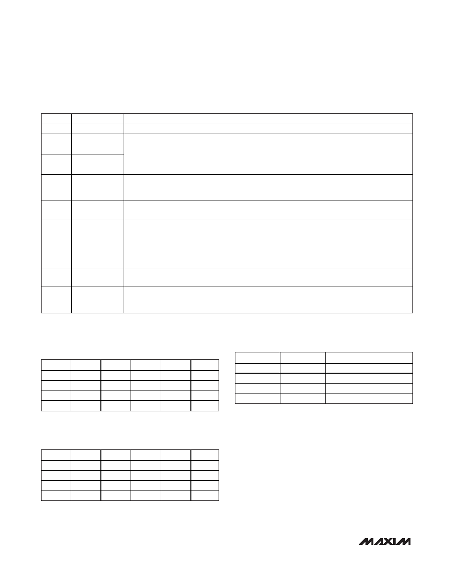
7 (MSB)
Setup
Setup byte always starts with 1.
6
REF/AIN SEL1
5
REF/AIN SEL0
When [0,0], REF/AIN3 = AIN3, REF = VDD.
When [0,1], REF/AIN3 = REF, REF = external reference.
When [1,0], REF/AIN3 = AIN3, REF = internal reference.
When [1,1], REF/AIN3 = REF, REF = internal reference.
(Table 3)
4
INT REF Power
Down
1 = internal reference always powered up.
0 = internal reference always powered down.
(Table 3)
3
INT/EXT Clock
0 = internal clock.
1 = external clock (MAX1361/MAX1362 use the SCL clock for conversions).
2
UNI/BIP
0 = unipolar.
1 = bipolar.
Selects unipolar or bipolar conversion mode. In unipolar mode, analog signal in 0 to VREF range
can be converted. In differential bipolar mode, input signal can range from -VREF/2 to +VREF/2.
When single-ended mode is chosen, the SE/
DIF bit of configuration byte overrides UNI/BIP, and
conversions are performed in unipolar mode.
1
Reset
1 = no action.
0 = resets
INT and configuration register. Setup register and channel trip thresholds are unaffected.
0
Monitor Setup
0 = no action.
1 = extends writing up to 13 bytes (104 bits) of alarm reset mask. Scans speed selection and
alarm thresholds. See the Configuring Monitor Mode section.
Table 4. Setup-Byte Format*
*
Power-on defaults: 0x82
CS1
CS0
CH0
CH1
CH2
CH3
00
+
01
+
10
+
11
+
Table 5. Channel Selection in Single-
Ended Mode (SE/DIF = 1)
CS1
CS0
CH0
CH1
CH2
CH3
00
+
-
01
-
+
10
+
-
11
-
+
Table 6. Channel Selection in Differential
Mode (SE/DIF = 0)
SE/DIF
UNI/BIP
MODE
0
Differential inputs, unipolar
0
1
Differential inputs, bipolar
1
0
Single-ended inputs, unipolar
1
Single-ended inputs, unipolar
Table 7. SE/DIF and UNI/BIP Table
发布紧急采购,3分钟左右您将得到回复。
相关PDF资料
MAX1364MEUB+T
IC SYSTEM MON 12BIT 4CH 10-UMAX
MAX1394ETB+T
IC ADC 8BIT 416KSPS 10-TDFN-EP
MAX1395ETB+T
IC ADC 10BIT 357KSPS 10-TDFN
MAX1400CAI+
IC ADC 18BIT LP 28-SSOP
MAX1401CAI+
IC ADC 18BIT LP 28-SSOP
MAX1415AEWE+T
IC ADC 16BIT DELTA SIGMA 16-SOIC
MAX1421CCM+D
IC ADC 12BIT 40MSPS 48LQFP
MAX1426EAI+T
IC ADC 10BITS 10MSPS 28SSOP
相关代理商/技术参数
MAX1361MEUB-T
功能描述:模数转换器 - ADC RoHS:否 制造商:Texas Instruments 通道数量:2 结构:Sigma-Delta 转换速率:125 SPs to 8 KSPs 分辨率:24 bit 输入类型:Differential 信噪比:107 dB 接口类型:SPI 工作电源电压:1.7 V to 3.6 V, 2.7 V to 5.25 V 最大工作温度:+ 85 C 安装风格:SMD/SMT 封装 / 箱体:VQFN-32
MAX1362EUB
功能描述:模数转换器 - ADC RoHS:否 制造商:Texas Instruments 通道数量:2 结构:Sigma-Delta 转换速率:125 SPs to 8 KSPs 分辨率:24 bit 输入类型:Differential 信噪比:107 dB 接口类型:SPI 工作电源电压:1.7 V to 3.6 V, 2.7 V to 5.25 V 最大工作温度:+ 85 C 安装风格:SMD/SMT 封装 / 箱体:VQFN-32
MAX1362EUB+
功能描述:模数转换器 - ADC 10-Bit 4Ch 150ksps 5.5V Precision ADC RoHS:否 制造商:Texas Instruments 通道数量:2 结构:Sigma-Delta 转换速率:125 SPs to 8 KSPs 分辨率:24 bit 输入类型:Differential 信噪比:107 dB 接口类型:SPI 工作电源电压:1.7 V to 3.6 V, 2.7 V to 5.25 V 最大工作温度:+ 85 C 安装风格:SMD/SMT 封装 / 箱体:VQFN-32
MAX1362EUB+T
功能描述:模数转换器 - ADC 10-Bit 4Ch 150ksps 5.5V Precision ADC RoHS:否 制造商:Texas Instruments 通道数量:2 结构:Sigma-Delta 转换速率:125 SPs to 8 KSPs 分辨率:24 bit 输入类型:Differential 信噪比:107 dB 接口类型:SPI 工作电源电压:1.7 V to 3.6 V, 2.7 V to 5.25 V 最大工作温度:+ 85 C 安装风格:SMD/SMT 封装 / 箱体:VQFN-32
MAX1362EUB-T
功能描述:模数转换器 - ADC RoHS:否 制造商:Texas Instruments 通道数量:2 结构:Sigma-Delta 转换速率:125 SPs to 8 KSPs 分辨率:24 bit 输入类型:Differential 信噪比:107 dB 接口类型:SPI 工作电源电压:1.7 V to 3.6 V, 2.7 V to 5.25 V 最大工作温度:+ 85 C 安装风格:SMD/SMT 封装 / 箱体:VQFN-32
MAX1362LEUB+T
制造商:Maxim Integrated Products 功能描述:ADC SGL SAR 150KSPS 10-BIT SERL 10PIN UMAX - Tape and Reel
MAX1362LEUB-T
制造商:Maxim Integrated Products 功能描述:4-CHANNEL, 10-BIT, SYSTEM MONITOR WITH PROGRA - Tape and Reel
MAX1362MEUB
功能描述:模数转换器 - ADC RoHS:否 制造商:Texas Instruments 通道数量:2 结构:Sigma-Delta 转换速率:125 SPs to 8 KSPs 分辨率:24 bit 输入类型:Differential 信噪比:107 dB 接口类型:SPI 工作电源电压:1.7 V to 3.6 V, 2.7 V to 5.25 V 最大工作温度:+ 85 C 安装风格:SMD/SMT 封装 / 箱体:VQFN-32